Wednesday, September 30, 2009

TECH TIP

TOPIC: Using Save As with References

If a drawing or an assembly is needed which is similar to another but uses a few different components; using the save as command and changing the references, the components that need to be renamed can be before any changes are made.

Procedure
:
A small assembly is shown to the right in Figure 1. The bracket needs to be different. Rather than recreating the entire assembly from scratch, the Save As command will be used to change the assembly name as well as the bracket name.

1. Open the assembly that is similar to the desired result.

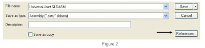
2. Go to File, Save As and select the References icon under the Cancel icon. See Figure 2.

3. Double click the names of the files that need to be different. In this case the assembly and bracket will receive new names. New files are shown in green. See Figure 3.

4. Select Save All.


Notes:
The More Options icon in Figure 3 enables adding a prefix or suffix to multiple files when selected.
The Name or Folder column can be selected to change all file names or location.
A different drawing can be saved using the same procedure.


TECH TIP

TOPIC: Text Borders

Borders can be placed around text in a drawing to manually create items
such as revision symbols or balloons.


Procedure: Use the note command.
Select the border box in the property manager.

Select the type of border Select the spacing around the text


Examples:


TECH TIP

TOPIC: Numbered or bulleted text

How is the spacing controlled between the numbers or bullets and text on a drawing?


Procedure: When editing the text, RMB and select “Bullets and Numbering . . .”


“First Line Indent” sets the space between the number or bullet and the text.


Notes: Lines can be controlled separately if so desired.
TECH TIP

TOPIC: Inspection Documents using eDrawings

SolidWorks enables the user to mark specific dimensions on drawings as inspection dimensions by placing an oval around the specific dimension value. eDrawings Professional offers a means to create an electronic version of this document for inspection purposes. This provides a means to document the measured values of these critical dimensions, maintain any notes related to the measurement method and securely store this information in an electronic format separate from the original SolidWorks source drawing.

Procedure:
From within eDrawings the native SolidWorks drawing file is opened and saved as an eDrawing document. Using the mark up functionality and associated comments the inspection document can be created, edited, and reviewed by others who can also reply to existing comments or add their own.

1. In eDrawings open the native SolidWorks drawing, detached drawings are supported as well, and save the file as an eDrawing file type. (.edrw)

2. Select the mark up icon from the left side of the screen to open the markup dialog panel. Each inspection can be listed here with comments that will appear in the bottom half of the panel. Also the various shapes for the inspection data can be selected from this panel as well a general notes.


3. Placing a rectangle in the graphics area and using text to record the measured value will generate a comment in the Markup Panel. A descriptive name can be applied and any text such as the measuring device used for this inspection can be added. The current “User Name” is applied automatically.


4. Selecting the comment will enable the Reply function. The current user can respond to individual inspection comments.


Notes:

1. The filename of the inspection document can be identical to the original native SolidWorks document.
2. PDM Enterprise can automate this creation process and also allow a specific workflow for the inspection document.
3. eDrawings also has “stamps” such as APPROVED which can be permanently applied to the file.
4. Markups can also be saved in external files separate from the .edrw file, where they can be imported at any time.

Tuesday, September 15, 2009

TECH TIP

TOPIC: Schedule a Defrag on multiple drives

One of the most over looked and easiest things to fix for system performance is defragmenting your disks. The problem is making the time to run it and if you have several disks then you have to wait for one to finish before starting the next. There are fee based software’s out there that can do this, but why spend the money. I found this tip on the Microsoft website and it works great.

Procedure:
Use the Window’s task scheduler with some minor task editing to add a drive letter. Not as obvious as you might think…


1. Click Start, and then click Control Panel


2. Click Performance and Maintenance

3. Under or pick a Control Panel icon, click Sheduled Tasks.


4. In the Scheduled Tasks window, double-click Add Scheduled Task.

5. In the Scheduled Task Wizard, click Next.

6. Click Browse

7. In the File name box, type %systemroot%\system32\defrag.exe and then click Open.

8. Under Perform this task, click Weekly. Then, click Next.

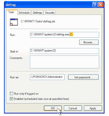
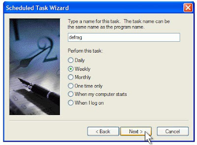
9. Set the time and day of the week you would like to defragment your hard drive. For best results, choose a time when your computer will be on but you will be away from it. Click Next.

10. Type your password in both the Enter the password and Confirm password boxes. Then, click Next.

11. Select the Open advanced properties for this task when I click Finish check box, and then click Finish.

12. In the Run box, add C: to the existing command. Make sure you include a space before the “C:”. Then, click OK.


13. In the Set Account Information dialog box, type your password in both the Password and Confirm password boxes. Then, click OK.

Windows XP will defragment your hard drive at the time you have scheduled. During defragmentation, a black window will open. If you happen to be working at your computer when the window opens, you can ignore it. The window will automatically disappear when defragmentation is complete. You can use other programs during defragmentation, but you may prefer to schedule defragmentation at a time when you won’t be using your computer.
Defragmentation works best when you have plenty of free space on your hard drive.

Notes:

Link to procedure from Microsoft (http://www.microsoft.com/windowsxp/using/setup/tips/defrag.mspx)


TECH TIP

TOPIC:
3D Drawing View Mode


3D drawing view mode will dynamically manipulate the model in a drawing view. It’s typically used to select items that are behind other entities.

Procedure: The command can be accessed from the heads-up view toolbar.


After selecting a view you can pan, zoom, or rotate. When you Exit, the view returns to its original orientation.Notes: It’s possible to save the orientation to be used in this or another view. The prerequisite for this functionality is that the view must be a named view.

To save the orientation press Spacebar before exiting the command and create a new view.

The new view will then be available to use in this or any other named view.


TECH TIP

TOPIC: Locking your dimension style with the right mouse button.

Sometimes one may want a dimension placed in an odd position other than horizontal or vertical, but maintain either the horizontal or vertical dimension orientation. This can be achieved easily if you watch your mouse feedback when placing the dimension.

Procedure:

During Sketching, the user can lock a dimension orientation when needed. This can be achieved by looking for the right click option symbol when placing a dimension.

1.Select the Smart Dimension Icon, and then select the items to be dimensioned then move to the desired location.

2. Look for the right click option symbol (shown below). When the dimension is in the desired orientation, hit the Right mouse button and lock this orientation.

a. Linear Dimensions:
b. Angular Dimensions:


3. The dimension can now be moved to any location, but will maintain the current orientation.

Notes: With many commands the user should watch the feedback options available.

1. When extruding a feature look for the green check mark option with the right mouse click. It’s faster than hitting the return key or selecting it from the confirmation corner.
2. If you go to tool, Sketch Tools, Modify