Monday, April 27, 2009

Tech Tip: Removing Tangent Edges from Sweeps with “Fit Spline”.

CATEGORY: Part

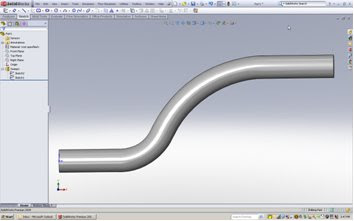
Have you ever created sweeps, but did not want tangent edges reflected throughout your sweep at every tangent point? You can remove tangent edges through this process:
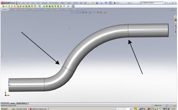
Before - Sweep reflects tangent edges.

After – Sweep reflect no Tangent Edges


Procedure:
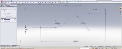
1. Edit the path of an existing sweep or when creating a path for a sweep, “right click” on the sketch and choose, “Select Chain”.
2. Go to the pull down menu and select: Tools, Spline Tools, Fit Spline (or add to short cut menu).
3. Exit the sketch or create your sweep with the new Spline.
4. The resulting “Swept feature” will no longer have tangent edges at each tangent point.
Notes:
Using a Spline initially would have worked also; however, you would not have standard radius dimensions, for arcs and curves if needed for manufacturing or 2D drawings.3D sketches are also very useful when creating sweeps. When creating a surface, a Spline also creates one continuous surface.


Friday, April 24, 2009


Making Data Management Simple with SolidWorks Enterprise PDM

MANAGE YOUR 3D DATA EASILY

Join us for this FREE seminar and explore how SolidWorks Enterprise PDM can help your company manage and share all the data related to your designs more effectively.

Patrick Brochu and Sylvain Trudel of SolidWorks will be joining us to provide valuable insight and answer any of your specific SolidWorks Enterprise PDM questions.

Learn about the benefits of implementing data management into your design process and how your design team can:
  • Manage product data effectively
  • Share design information without compromising integrity
  • Automate workflows
  • Improve collaboration between engineering and manufacturing

Attend and receive the free white paper, "PDM vs. PLM: It all Starts with PDM"

Register Today!

Thursday, April 16, 2009


ModernTech Mechanical Announces 3DVIA Composer Hands-On Test Drives

Attend a 3DVIA Composer Hands-On Test Drive to learn how to seamlessly incorporate design changes directly into your product documentation, and create up-to-date, accurate, printed and interactive materials. With 3DVIA Composer, your entire organization can automate and integrate the documentation process.


Using 3DVIA Composer you can:

  • Eliminate expensive errors and quickly update all product documentation through automation.
  • Get new products to market faster and gain a competitive advantage.
  • Leverage existing 3D designs in multiple CAD formats to produce accurate, up-to-date product documentation.
  • Enable technical and nontechnical staff to collaborate effectively during documentation production.
  • Improve customer service.

Easily create documents such as:

  • Assembly instructions.
  • Customer-service procedures.
  • Marketing materials.
  • User manuals.
  • Field-service repair manuals.
  • Training materials.
  • Web-based catalogs

Register Here: http://www.moderntechmech.com/seminars/handson_3dvia.html

Monday, April 6, 2009


Make your Layoff Payoff with ModernTech Mechanical


It hurts losing your job. You worked hard. You did the right things. You followed all the rules. Still, the economy dealt you a painful blow.


ModernTech Mechanical is here to give you a helping hand. ModernTech Mechanical has joined M Force - the employment professionals and SolidWorks - the leader in 3D CAD technology to bring you the Layoff Payoff Program.


The Layoff Payoff Program provides displaced engineers and designers with FREE SolidWorks 3D CAD software, training, Certified SolidWorks Associate (CSWA) certification opportunities, and job placement services. Created in conjunction with the SolidWorks Engineering Stimulus Package, develop, Upgrade, or Refresh your 3D skills today to help you find the right job.


Payoffs At-A-Glance:

  • SolidWorks Student Design Kit (includes fully-featured SolidWorks Standard) 90-day software trial

  • Free 3 hour hands-on test drive training in a classroom style setting (first-come, first served)

  • Certified SolidWorks Associate (CSWA) certificate (upon completion of passing exam)

  • Job seeker resource guide

  • Premium placement in M Force candidate database

  • Free career placement services through M Force

  • Discounts on Additional SolidWorks training from ModernTech Mechanical

  • Resume writing services from M Force

  • Software with subscription purchase (for you or your new employer) ModernTech Mechanical


Yes it’s free. No gimmicks. No catches. No bull.

To Learn More or Register:

http://www.moderntechmech.com/EngineeringStimulus.html

Tuesday, March 31, 2009

Tech Tip: Using ‘Select Other’ to select hidden faces, edges, or vertices.

Category: Productivity


It is often necessary to select a face, edge, or vertex that is hidden by other geometry. The Select Other tool allows us to quickly and easily hide any faces that are in front of the geometry we want to select.

Procedure:
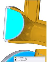
A section view has been applied to the part shown at the right. The face we want to select is shown in blue. The procedure for selecting this face without using section view is as follows.


Hover over the portion of the model that covers the desired face, RMC and choose Select Other. The face that was initially right clicked on will be hidden first. Other faces will remain visible.


With the Select Other tool open, any face the user right clicks on will be hidden from view. The user can continue hiding faces with right clicks until the desired selection face, edge, or vertex comes into view.


Once the desired selection face, edge, or vertex comes into view the user can left click on the entity to select it.


Notes:

The selection box that appears when using the Select Other tool can be used to select the faces as well. To use this box the user must make sure that the desired selection entity is directly behind the first entity that is selected when the tool is started. This will ensure that the entity will be listed in the selection box.
Tech Tip: Simple ways to control a 3D Spline

Category: 3D Splines


Many times during sketching, we have to create splines. If the spline follows along a pre-defined plane it is not too difficult, however there are times when you may want it to move in other directions. Additionally, we tend to create splines with too many points. Next time keep the points to a minimum and adjust the position with multiple view ports.

Procedure:

Start a 3DSketch, select spline and proceed to sketch. Remember to keep the qty of point to a minimum.


Split your screen into 4 view ports, and adjust as needed. You can use the triad to reposition your spline for greater control.


Notes:

  1. There are many other tools to help you adjust your splines, just click on it.
  2. Remember to practice often, and try to use 3d sketching more frequently.
Tech Tip: Renaming Referenced Configurations

Category: It’s About Time


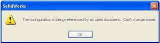
Ever try to rename a configuration and get this error?


New in SolidWorks 2009 Service Pack 2.0 (and higher) is the ability to rename referenced configurations.

Procedure:

  1. With the part or assembly open, as well as the document referencing the configuration to be renamed, highlight the configuration and either slow double click, or press <F2> to rename it.
  2. Navigate to the referencing document so that the drawing view or assembly component can read the new name.
  3. Click OK to the following warning message:

Notes:

  1. This has been tested with parts and assemblies being referenced by drawings and higher level assemblies.
  2. This is not known to be available prior to Service Pack 2.0.
  3. This enhancement is not documented in the Fixed SPR’s.