Thursday, April 30, 2009

TECH TIP: Selecting edges for surface sweep path

Using model edges for the path on a surface sweep saves time by eliminating the need to create another sketch. However sometimes the entire edge is not desired, only a small portion is required for the sweep. In this situation using “Selection Manager” enables the ability to use only a portion of the edge.

Procedure:

These two images show the creation of a surface sweep along the edge of an existing surface. The standard selection of an edge as the path is shown on the left, and the Selection Manager method on the right.


  1. Start the surface sweep command and select the profile as usual.
  2. Right mouse click to invoke the Selection Manager option. Using the Select Group option, select the edge.
  3. Prior to acceptiong the Selection Manager, drag the end of the path along the edge.
  4. OK the Selection Manager and the Sweep command.


Notes:

  1. Only drags along the selected edge are supported in this technique
  2. The endpoint that is coincident with the profile must remain so.
  3. Object snaps can be used to specify the endpoint of the dragged profile.


TECH TIP: Using Trim Entities sketch tool to extend sketched lines

CATEGORY:
Part

The Trim Entities sketch tool can also be used to extend sketch lines.


Procedure:
When using the Trim Entities sketch tool pictured below,


there are five trim options as shown on the right. When using the Power trim option, the trim tool can be also be used to extend a line to the next entity.


The sketch below has its entities labeled to be trimmed or extended. This can be accomplished easily using the Power trim option with extend capability.


The first step is to start the Trim Entities tool and select the Power trim option. To trim entities using this option, press and hold the left mouse button and drag the cursor over the entities to be trimmed. Every line the cursor crosses over will be trimmed to the next intersecting entity. See sketch below.


After the trimming is done, continue to hold the left mouse button down, press and hold the Shift key, and drag the cursor over the line to be extended. The line will be extended until it hits the next sketch entity. See sketch below.


Wednesday, April 29, 2009

Tech Tip: Dimensioning to an arc-shaped cut of a cylinder

A warning may appear when trying to add a dimension in the drawing to an arc-shaped cut of a cylinder.

The feature was made by extruding a cut with the following sketch.
Procedure: One way to dimension the drawing is to expand the drawing view in the feature manager and show the sketch. A dimension can be added to the sketch entities and afterwards the sketch can be hidden.

Notes:
Another solution is to create a section view. The section view can be dimensioned without a warning.


Tuesday, April 28, 2009


ModernTech Mechanical's Layoff Payoff Program Featured on WBIR News Knoxville, TN

Click HERE to watch the video!

Monday, April 27, 2009


Webinar: Beat the Recession with DriveWorks Express

Wednesday, April 29, 2009 10:00 AM - 11:00 AM EDT


ModernTech Mechanical is pleased to announce our Beat the Recession with DriveWorks Webinar- Making the most of the tools you have in SolidWorks.
  • Are the products you design the same but different?
  • Do you have repetitive design tasks that could be automated?
  • Could your products be defined by a set of rules?

If the answer is YES to any of these questions, then DriveWorks and SolidWorks could help you dramatically improve your productivity via Design Automation... and the good news is that as an existing SolidWorks user, you already have some of these tools available to you via DriveWorksXpress, which is included in every license of SolidWorks.

And as a special gift to all those who attend, we are pleased to give you FREE copy of the Little Book of Rules - the definitive guide to working with rules to automate your design process.

Register Here: https://www2.gotomeeting.com/register/327733015
Tech Tip: Removing Tangent Edges from Sweeps with “Fit Spline”.

CATEGORY: Part

Have you ever created sweeps, but did not want tangent edges reflected throughout your sweep at every tangent point? You can remove tangent edges through this process:

Before - Sweep reflects tangent edges.

After – Sweep reflect no Tangent Edges
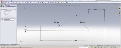

Procedure:
1. Edit the path of an existing sweep or when creating a path for a sweep, “right click” on the sketch and choose, “Select Chain”.
2. Go to the pull down menu and select: Tools, Spline Tools, Fit Spline (or add to short cut menu).
3. Exit the sketch or create your sweep with the new Spline.
4. The resulting “Swept feature” will no longer have tangent edges at each tangent point.
Notes:
Using a Spline initially would have worked also; however, you would not have standard radius dimensions, for arcs and curves if needed for manufacturing or 2D drawings.3D sketches are also very useful when creating sweeps. When creating a surface, a Spline also creates one continuous surface.