Tuesday, March 31, 2009

Tech Tip: Using ‘Select Other’ to select hidden faces, edges, or vertices.

Category: Productivity


It is often necessary to select a face, edge, or vertex that is hidden by other geometry. The Select Other tool allows us to quickly and easily hide any faces that are in front of the geometry we want to select.

Procedure:
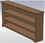
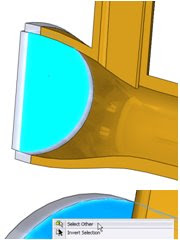
A section view has been applied to the part shown at the right. The face we want to select is shown in blue. The procedure for selecting this face without using section view is as follows.


Hover over the portion of the model that covers the desired face, RMC and choose Select Other. The face that was initially right clicked on will be hidden first. Other faces will remain visible.


With the Select Other tool open, any face the user right clicks on will be hidden from view. The user can continue hiding faces with right clicks until the desired selection face, edge, or vertex comes into view.


Once the desired selection face, edge, or vertex comes into view the user can left click on the entity to select it.


Notes:

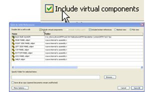
The selection box that appears when using the Select Other tool can be used to select the faces as well. To use this box the user must make sure that the desired selection entity is directly behind the first entity that is selected when the tool is started. This will ensure that the entity will be listed in the selection box.
Tech Tip: Simple ways to control a 3D Spline

Category: 3D Splines


Many times during sketching, we have to create splines. If the spline follows along a pre-defined plane it is not too difficult, however there are times when you may want it to move in other directions. Additionally, we tend to create splines with too many points. Next time keep the points to a minimum and adjust the position with multiple view ports.

Procedure:

Start a 3DSketch, select spline and proceed to sketch. Remember to keep the qty of point to a minimum.


Split your screen into 4 view ports, and adjust as needed. You can use the triad to reposition your spline for greater control.


Notes:

  1. There are many other tools to help you adjust your splines, just click on it.
  2. Remember to practice often, and try to use 3d sketching more frequently.
Tech Tip: Renaming Referenced Configurations

Category: It’s About Time


Ever try to rename a configuration and get this error?


New in SolidWorks 2009 Service Pack 2.0 (and higher) is the ability to rename referenced configurations.

Procedure:

  1. With the part or assembly open, as well as the document referencing the configuration to be renamed, highlight the configuration and either slow double click, or press <F2> to rename it.
  2. Navigate to the referencing document so that the drawing view or assembly component can read the new name.
  3. Click OK to the following warning message:

Notes:

  1. This has been tested with parts and assemblies being referenced by drawings and higher level assemblies.
  2. This is not known to be available prior to Service Pack 2.0.
  3. This enhancement is not documented in the Fixed SPR’s.
Tech Tip: Assembly Starter File with Virtual Parts

Category: Assembly


Creating an assembly starter file including virtual parts can makes for a quick and easy way to create derivative designs. With virtual parts, only a single assembly file is needed for the starter file which will create all the individual part files when using the references option of “save as”.

Procedure:

Create an assembly file with only Virtual parts. In context features are optional but using them with assembly sketches can add to the functionality. Save this file with a generic name, for this example Book Shelf will be used.


Open the Basic assembly and select File/Save As. In the Save As dialog box, select References and check the Include Virtual Components box.


Select all the files by selecting the column header Name. Under More Options, add a suffix such as _Customer A. Optionally a destination folder for the new parts can be specified. Select Apply to see a preview of the new filenames and paths listed in green. Select Save All to complete the process.


The new assembly and individual part files are created with the new names. The original starter file is left unchanged.
Tech Tip: Equations and Custom Properties

Category: Parts

Custom properties can be used in equations and equation variables can be accessed in custom properties.

Procedure:

Example: We know the cost per pound of the material we’re using. We would like a custom property for the total cost of the part which can be determined by multiplying the cost per pound, times the weight of the part. First, we should create the custom properties “cost per pound” and “weight”.

We can calculate the total cost by creating an equation and accessing the custom properties from the drop-down at the bottom of the equation dialog box.


Then we can create a new custom property “cost” and set it equal to the equation variable.


Monday, March 30, 2009

Service Pack 3.0

Weldments
When two structural members intersect with a butt corner type, you can use options in the Structural Member and Trim/Extend PropertyManagers to make a:

  • Simple Cut: Makes the structural members flush with the planar contact faces (helpful for manufacturing)
  • Coped Cut: Trims the structural member to the contact body

Focal Length Support in PhotoView 360
A new control, Set Camera Focal Length in the Settings dialog, lets you control the focal length of the camera, resulting in different levels of perspective.

Print Selection and Scaling Options
The missing print selection workflow from SolidWorks 2008 has been restored. To print drawing selections at the desired scale:

  1. Click File, Print.
  2. In the Print dialog box, under Print range, select: Current screen image, Selection
  3. Click OK.
  4. In the Print Selection dialog box, set the print scale and click Apply Scale.
  5. Move the selection frame that appears in the graphics area as desired.
  6. Click OK to print.


Pro/ENGINEER Wildfire 4.0 Support
You can open Pro/ENGINEER® Wildfire 4.0 files in SolidWorks.

New SolidWorks and SolidWorks Simulation Tutorials
SolidWorks

  • DimXpert
  • Electrical Routing
  • TolAnalyst

SolidWorks API

  • C#
  • VB.NET


SolidWorks Simulation

  • Design Check for Assembly with Mixed Mesh
  • Design Check for Connectors


Click Help, SolidWorks Tutorials to access the SolidWorks and SolidWorks API tutorials. Click Simulation, Help, Simulation Online Tutorial to access the SolidWorks Simulation tutorials. The new tutorials are not localized. The English version is accessible from all localized versions of SolidWorks. Updated tutorials and documentation are available in complete installations of SolidWorks 2009 Service Pack 3.0.


Renaming Configurations
You can rename a configuration in a part or subassembly even when another open document is referencing the configuration. Previously, you had to close the parent document before renaming the configuration. This functionality was introduced in SP 1.0.